
ALERT!
This site is not optimized for Internet Explorer 8 (or older).
Please upgrade to a newer version of Internet Explorer or use an alternate browser such as Chrome or Firefox.
Catheter-Based Mitral Intervention Imaging and Procedural TEE
Chen C, Okoh A, Garg A, Russo M. Catheter-Based Mitral Intervention imaging and Procedural TEE. November 2020. doi:10.25373/ctsnet.13229207
Summary
The catheter-based mitral intervention, particularly MitraClip, has become an important alternative to surgical repair or replacement of the mitral valve in patients with significant mitral regurgitation. The field of mitral valve intervention is rapidly evolving and thus requires more frequent updates of details and precision of cardiac imaging for the needs of the intervention. Currently, the primary imaging modality for assessment of mitral valve intervention is echocardiography. However, the role of other advanced cardiac imaging modality such cardiac MRI and cardiac CT will increase over time. The current review describes the optimal patient’s selection criteria, outlines a step-by-step approach with procedural imaging guidance, and defines the role of a heart team approach in achieving optimal outcomes.
Overview
More than 100,000 patients worldwide have undergone the MitraClip procedure. Studies have underlined the therapeutic benefit of the MitraClip system for patients at extreme and high risk for mitral valve surgery, suffering from either degenerative or functional mitral regurgitation (1). Moreover, the MitraClip procedure has shown high procedural success and low periprocedural complication rates, and a significant reduction in mitral regurgitation, as well as an improvement in functional capacity and most importantly, quality of life, re-hospitalization rates, and mortality (1-2). It hereby widens the spectrum of mitral valve repair and more options for treating significant MR for the heart team. Data from a variety of sources demonstrate that the MitraClip system is an effective and safe treatment in patients with moderate to severe or severe MR by an experienced heart team (1). However, there is a significant learning curve associated with the MitraClip implantation which suggests this therapy should be performed in centers of excellence with recognized surgical and structural expertise in mitral valve pathologies. Patient selection and detailed assessment of mitral valve pathology and mechanism of MR are vital for a successful mitral clip procedure. Providing clear TEE images of mitral structures and MitralClip device components intra-operatively for guidance and monitoring of the device advancement and placement, and cohesive interaction by clear communication between intraoperative TEE imager and device implanter (cardiac surgeon/interventional cardiologist) are an integrated part of successful MitraClip implantation.
The MitraClip Device

Figure 1: MitraClip system (A) consists of two components: steerable guide catheter (SCG) (B) and clip delivery system (CDS) (C).
Both implanter and imaging are required to be very familiar with the device system. The MitraClip system (Figure 1) consists of
- Stabilizer
- Steerable Guide Catheter (SGC)
- Clip Delivery System (CDS)

Figure 2: Clip delivery system (CDS) has three components: Delivery catheter handle, steerable sleeve handle and MitraClip device which includes two symmetrical clip arms and grippers.
CDS (Figure 2) consists of three components with steerable sleeve handle, delivery catheter handle, and mitral clip device. The clip device has clip arms and grippers. Detailed function and manipulation of the MitraClip system are illustrated in Figure 3. The steerable guide cath (SGC) can be manipulated with (A) posterior and (B) anterior torques primarily to manipulate the device towards posterior or anterior direction with associated effect of gaining or shedding height, and (C) plus (+) and minus (-) knobs primarily to gain or shed height with secondary effects of towards medial location and gaining height or towards lateral location and shedding height.
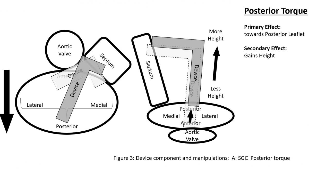
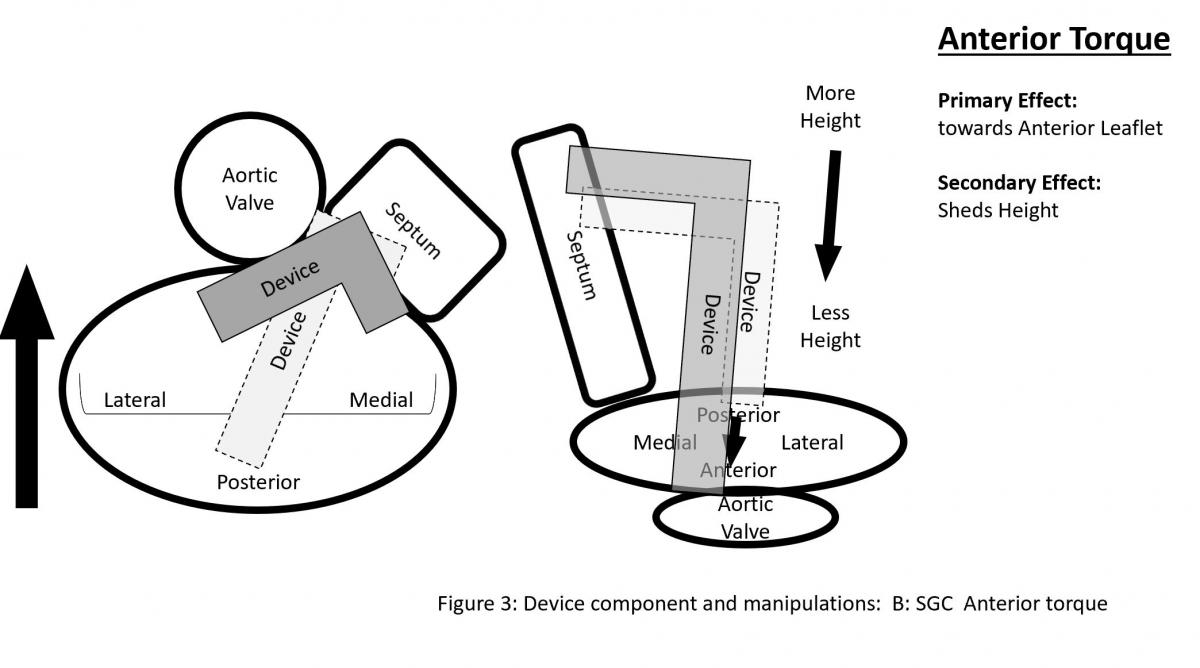


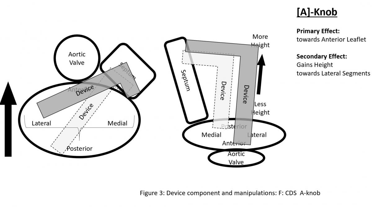
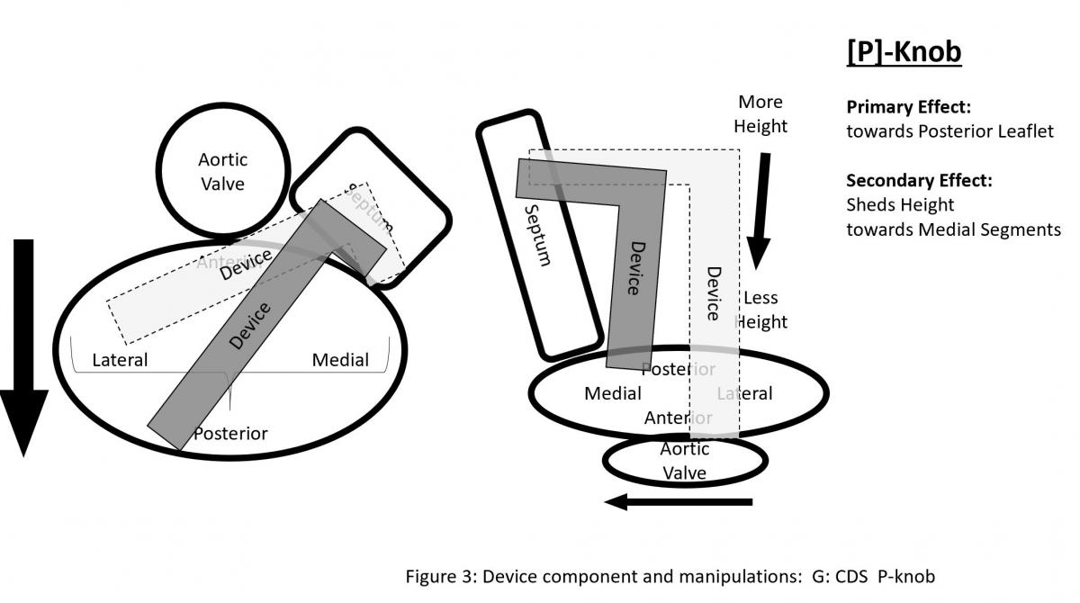
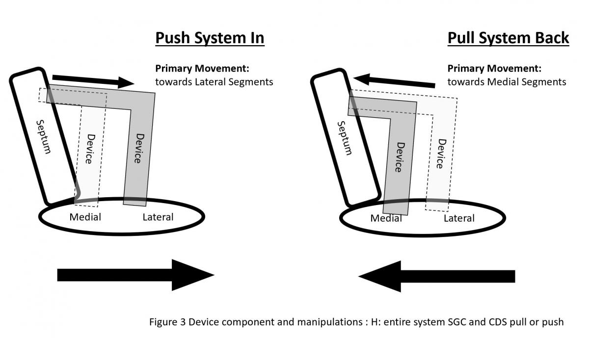
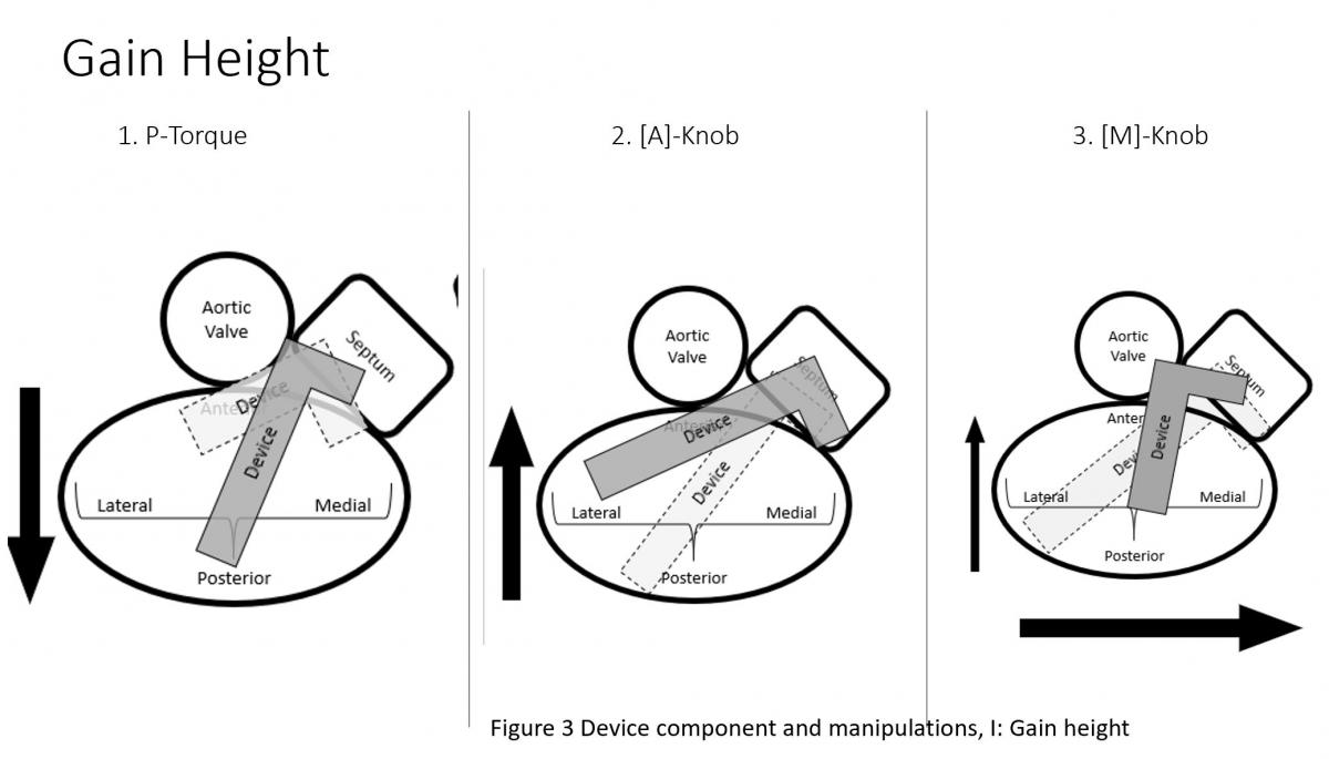
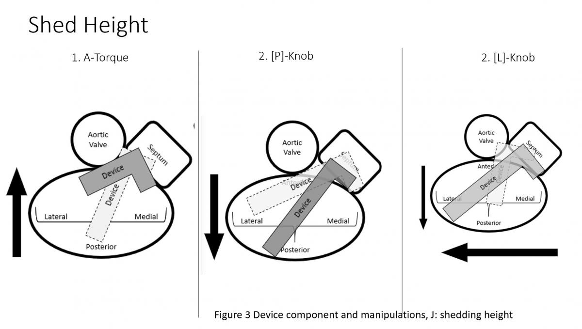
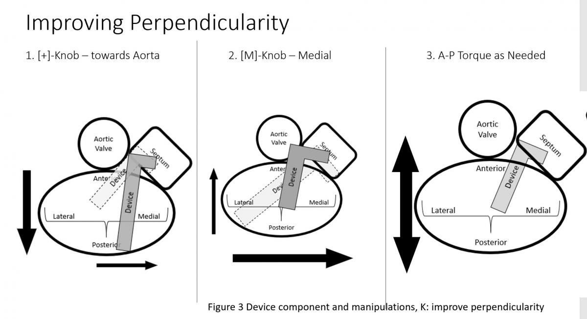
Figure 3: Device component and manipulations: A: SGC Effects of posterior torque, B: effects of SGC Anterior torque, C: SGC: +/- knobs, D: effects of CDS M-knob, E: effects of CDS L-knob, F: functions of CDS A-knob, G: function of CDS P-knob, H: function of entire system SGC and CDS pull or push, I: Strategy of maneuvering to gain height, J: Strategy of maneuvering to shed height, K: Strategy of maneuvering to be more perpendicular to the coaptation line.
The clip delivery system (CDS) (Figure 3) consists of several components for device manipulations to desired position in sync with SGC maneuvers. M-knob (D) has primary effect of towards medial segment with shedding height and L-knob (E) towards lateral direction with gaining height. Intuitively, the A-knob (F) is towards anterior and P-knob (G) towards posterior. Secondary effects of A-knob are gaining height and towards lateral and P-knob is shedding height and towards medial. Medial or lateral location of the device can also be manipulated by pushing or pulling the entire device system (SGC and CDS) together (H).
Brief Overview of Operative Steps
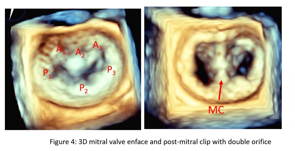
Figure 4: 3D TEE: enface view of mitral valve before (left) in systole and after mitral clip (right) in diastole. Note: a mitral clip tissue bridge (MC) divide the native mitral valve into double orifice of mitral valve. A: Anterior mitral leaflet, A1-A3 from lateral to medial with aorta at 12 o’clock, P: Posterior mitral leaflet with P1-P3 from lateral to medial.

Figure 5: TEE biplane (XPlane) commissure view (left) and LVOT view (right). On the left, the mitral commissure view, the MitraClip delivery catheter is shown to be positioned at the mid A2 and P2 location. On the left, left ventricular outflow tract (LVOT) view, both arms of clip device under mitral leaflet in the ventricular side (LV) which is visualized in the full length and grippers above the leaflet in the atrial side (LA).
After gaining transseptal access, the SGC enters the femoral artery and is passed into the IVC then RA then LA under TEE and fluoroscopic guidance. Then, the Clip Delivery System (CDS) is introduced through the SGC. The distal portion of the MitraClip catheter system has two arms that form a clip when closed. During the procedure, the clip arms are opened in the left ventricle, and during a pull-back toward the left atrium, the central portions (A2/P2) of the anterior mitral leaflet (AML) and the posterior mitral leaflet (PML) (Figure 4) are entrapped in the clip arms then by lowering corresponding secure grippers on atrial side of the leaflets to ensure the leaflet is sandwiched between clip arm and gripper (Figure 5), clips are closed, most often creating a double mitral orifice (Figure 4) and a significant reduction in MR.
Patient Selection
Indication: Currently, the MitraClip system is used in patients with severe mitral regurgitation who are:
(a) deemed at high risk for surgery in degenerative or primary mitral valve regurgitation (PMR) and
(b) secondary or functional mitral regurgitation (FMR) in heart failure patients who will not or cannot undergo surgical repair or replacement after guideline directed optimal medical therapy.
Primary vs Functional MR
Mitral regurgitation can be divided into primary and secondary. Table I. Structural abnormality to cause MR is classified as primary MR (PMR) or degenerative MR. Functional MR (FMR) is referred to MR with grossly normal mitral valve structure with apically tethered chords due to regional or global LV dysfunction and/or LV dilatation. Mitral annulus is often dilated in FMR. However, clinically, mitral regurgitation is not uncommon to have mixed etiology. Both the severity of MR and anatomical eligibility criteria are to be met in addition to clinical assessment of significant MR. For functional MR, the COAPT trial criteria should be used as reference (3). For Degenerative or primary structural MR (PMR), EVEREST II criteria should be used as reference (4).
Primary and secondary MR is not just morphologically different from each other but also have difference in MR jet characteristics and remodeling of LV and LA and they may coexist with mixed etiology of MR to have features of both PMR and FMR.
Specific assessment of features of the mitral valve for clip procedure:
- Location of MR,
- MV size/area,
- leaflet motion,
- leaflet calcification/thickening,
- Posterior Leaflet Length,
- Coapation Length and Depth (mitral leaflet end systolic tenting depth)
- Flail Gap and Width
Based on these features, the outcome of a mitral clip procedure can be estimated as favorable, challenging and unfavorable or contraindicated (Table II). This would be incorporated in the decision of treatment options for a patient in addition to surgical risk and expected outcome of patient’s need whether it is surgical mitral valve surgery or percutaneous catheter based mitral clip or other catheter based procedures. Eligibility and complexity of mitral clip are based on the above features as summarized in Table II.
Preprocedural Planning for MitraClip

Figure 6: Illustration of TEE probe with its steerability and ability to image different components of mitral leaflet structures. A: Steerability of the TEE probe, sector angle rotation from 0o to 180o, probe rotation, anterior flex (anteflex) and posterior flex (retroflex) of the probe and medial (left) and lateral (right) flex of the probe), potential views of TEE in the mid esophageal position with manipulation of steerable TEE probe. Ao: Aortic valve/aorta, LAA: left atrial appendage, 4CH: 4-chamber view of mid esophageal TEE probe position with probe sector rotation at 0-10 degree, CM: commissure view of mitral valve with 50-70 degree of sector angle rotation, with anteflex and retroflex of the probe from CM view, CMa and MCp can be obtained (C). CMa: anterior to CM view (Figure C lower, MCp: posterior to CM view (Figure C, lower), 2CH: 2-chamber view with TEE probe sector rotation of 80-100 degree, LVOT view or LV long-axis view with sector angle rotation of 120-150, LVOTm: medial to LVOT view with probe medial rotation or flex with or advancing the probe, LVOTl with probe lateral rotation or flex or pulling back of the probe (Figure C, upper). Posterior mitral leaflet is segmented into P1, P2 and P3 from the aorta/LAA anterolateral to inferomedial direction, Similarly, anterior leaflet is divided into A1, A2, A3 accordingly. Note: anatomic separation is present for posterior leaflet and no anatomic marker to separate A1 to A2 or A2 to A3.
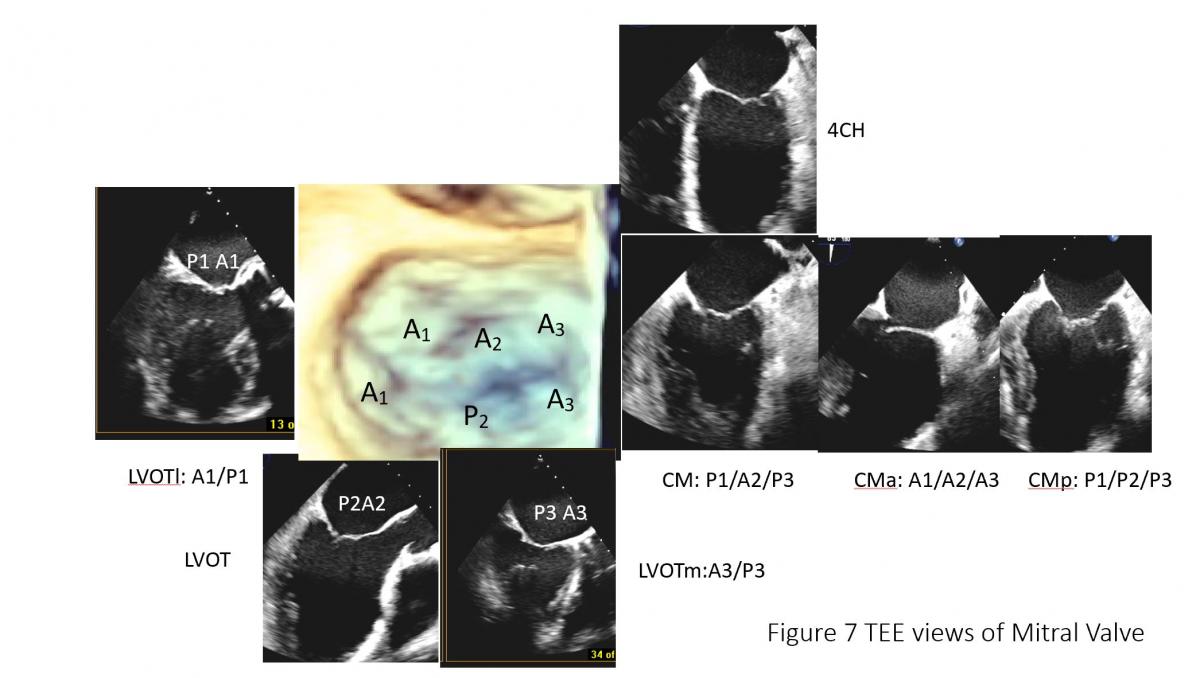
Figure 7: TEE of mitral valve: mitral leaflet segments on common of TEE views. CM: Commissural view of mitral valve (60 degree), CMa: anterior rotation to obtain CMa with A1A2A3, posterior rotation (CMp) to obtain P1P2P3, LVOT view with A2 and P2 and LVOT lateral maneuvering to get LVOTl with A1and P1 and LVOTmedial maneuvering to get P3 and A3 segment of mitral leaflets.
Selection of anatomically and mechanistically suitable patients for MitraClip will largely determine procedural success and short-term outcomes. Currently anatomy and mechanism of mitral regurgitation is primarily evaluated by detailed TEE assessment of mitral valve (Figures 6-7). Cardiac CT (Figure 8) can be used when there is requirement for better assess leaflet calcification if TEE is uncertain. It is important to have standard imaging protocol and terminology for communication between TEE imager and implanter prior, during and post clip for procedural efficiency, procedural success and outcome of the intervention.

Figure 8: Mitral leaflet segmentation is illustrated in cardiac CT views which is equivalent to corresponding TEE views which can be useful in orientation and in case of leaflet calcification for preprocedural planning. CT can also provide views for fluoroscopic view of projection of each segment of mitral leaflets.
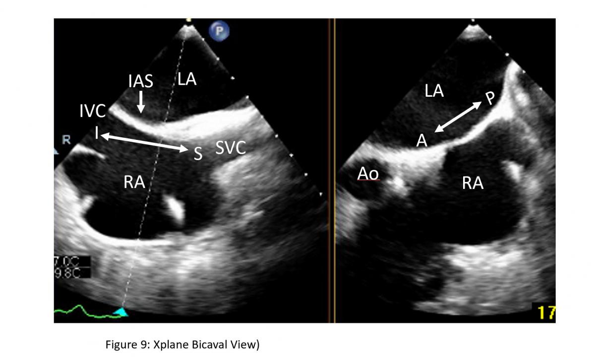
Figure 9: Bicaval view and short-axis view of interatrial septum on a Xplane TEE image: Bicaval view for superior as noted by superior vena cava (SVC) ) and inferior noted by inferior vena cava (IVC) direction of interatrial septum (IAS) can be obtained from TEE probe section rotation at 100-120 degree with medial rotation of the probe at mid esophageal level. LA: left atrium, RA: right atrium, Ao: aorta
To facilitate the communication, both echocardiographer and implanter should be familiar with essential TEE imaging views during mitral clips (Figures 6-8). For transseptal guidance, bicaval TEE view and short-axis basal heart (aortic valve) view are commonly used and often in a XPlane/biplane view (Figure 9). For device advancement guidance in the LA to mitral valve oblique 45 degree view of left pulmonary vein, left atrial appendage/coumardin ridge is often used (Figure 9). For mitral valve, 4-chamber (Figure 7), commissure 2-chamber view (Figures 7-8), LVOT long-axis or 3-chamber view (Figures 7-8) are most commonly used. Off axis 2-chamber views (Figures 7-8) and off-axis LVOT views (Figures 7-8) are used to see P1/A1 and P3/A3 segments of mitral valve. 3D TEE of en face mitral valve view with and without color Doppler flow mapping (Figure 10) is used to guide positioning clip system and clip arm alignment.
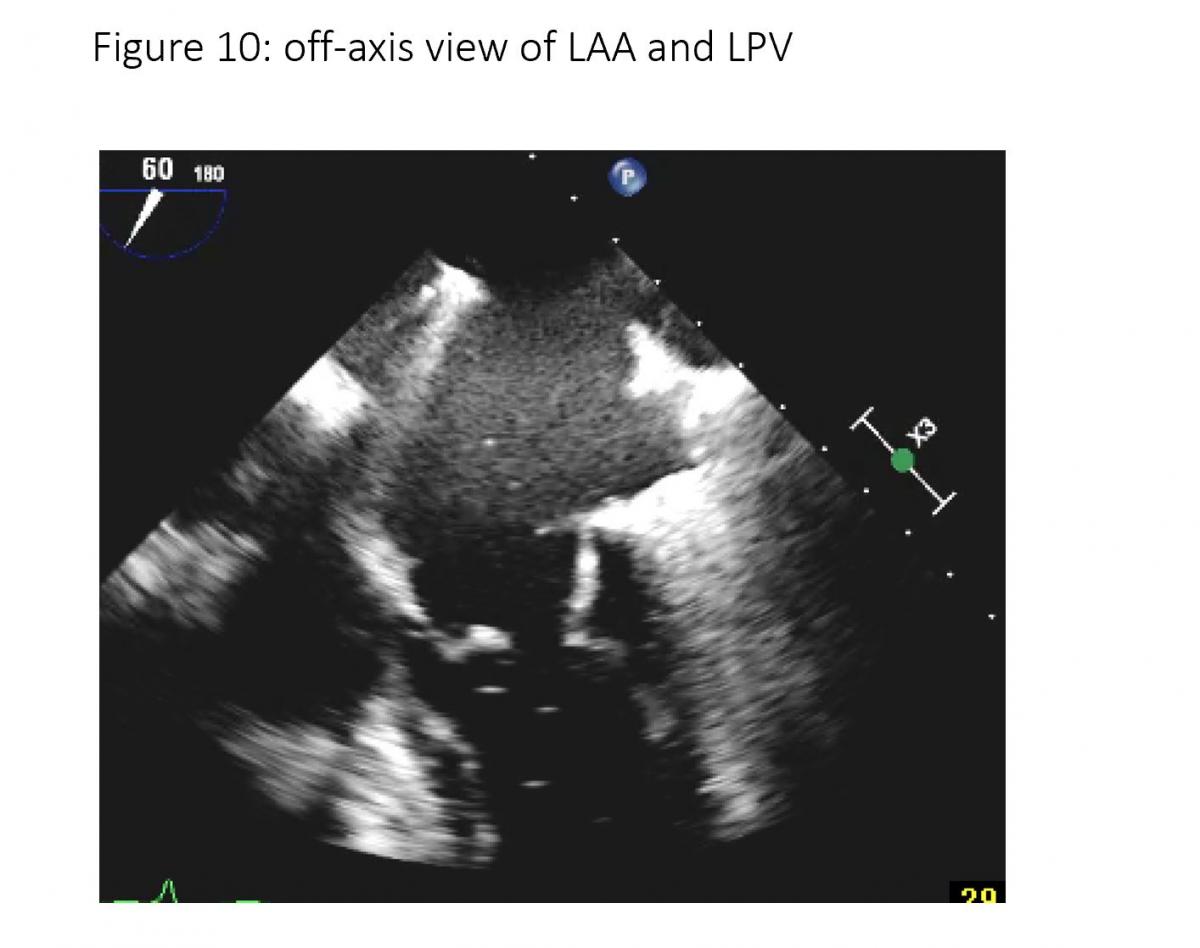
Figure 10: 45-70 degree views of PV (left pulmonary vein) and LAA (left atrial appendage).
Planning for the clip procedure requires definition of:
- mitral valve morphology
- specific pathology, etiology and mechanism that causes regurgitation (PMR or FMR).
- location of mitral leaflet lesion to cause MR for PMR
- clip device arm is long enough to grasp anterior and posterior leaflet gap from prolapsing/flail segment and width of flailed or prolapsing segment for PMR
- adequate tissue to grasp (length of posterior or anterior leaflet at grasping site for PMR and depth/distance to the coaptation point of valve leaflets for FMR.
This is not only crucial to determine the appropriate clip landing site, but also dictates the ideal transseptal puncture point (4).
MitraClip Procedure Steps and Interactive Procedural TEE
Detailed and stepwise interactive corparation between cardiac TEE imager and implanters (cardiothoracic surgeon and/or interventional cardiologist) are summarized in following table:
| Steps | Device Implanter and Imager | Echo View |
| Access - Venous puncture + Transseptal puncture | Watch for tenting as marker of septal needle tip pressing perpendicularly to IAS which is transseptal location (TS), preferred transseptal location of superior to mid and posterior location. TS height
| 2D TEE biplane simultaneous x-plane views including:
|
| Insert the delivery system | Secure guiding wire in LPV. Consider ballooning with a 10-12mm mustang balloon. After securing the wire in the LPV CDS system is advanced with SGC (steerable guiding catheter (sheath) with a dilator. Insert SGC to 2cm beyond IAS and withdraw the dilator. Tip of SGC is marked with echogenic groove. Direct SGC toward lateral direction to avoid hitting aortic root wall anteriorly and LA roof posteriorly. |
|
| Insert the CDS and steer the device | Watch under TEE and fluoroscopy to advance Mitraclip device out of SGC and to make sure tip of the device (clip arm) is imaged in its long-axis to avoid hitting atrial free wall, aortic root or coumadin ridge or entering into LAA. After straddling the device, bypass the coumadin ridge/LAA via a posterior torque of the SGC and simultaneous medial deflection of the CDS accompanied by retraction of the whole system. These steps are done under fluoroscopic guidance. |
|
| Identify location of the pathology and position of CDS | Move CDS to location of pathology and down to close to mitral annulus (1 cm above mitral annulus) and to the desired location. (eg, anterior/posterior, medial/lateral) The trajectory is checked on orthogonal two plane view of 2D TEE (X-plane view); the intercommissural view (primary image), and the left ventricular outflow tract (LVOT) view to ensure the steerable distal part of the clip device is perpendicular to desired coaptation line of mitral valve. | 4 chamber views at 0 degrees. 2 chamber view at ~60 degrees also known as the commissural view with the P1, A2, and P3 scallops visible and LVOT view at 125 degree. Biplane/x plane commissure view/LVOT view, 3D live of the device on en face MV view with 3D zoom can be helpful for checking device trajectory. |
| Position and Orient the clip | Open arms Rotate clip orientation is perpendicular to the line of mitral valve coaptation (eg. for A2/P2 with 12/6 o’clock orientation of the arms). | 3D zoom for enface view of mitral valve 60 degree commissure view of mitral valve for clip device position, LVOT view with 125-145 degree for orientation of the clip arm. Biplane Xplane: commissure/LVOT view |
| Grasp of the leaflets |
| LVOT grasping view (125 degree) Or Xplane commissural view/LVOT view 3D zoom of en face mitral valve and clip in LV with reduced gain to eliminate echo of mitral valve and just seeing the clip arm |
| Assess + Repeat? | Result
Grasp
Questions
|
|
| Removal of Device | Watch the device tip to ensure not to hit LA free wall while withdrawing the device after releasing the clips. | Commissural/LVOT views, Short-axis and long-axis 45 degree views for LAA/coumadin ridge and aortic root wall. |
Integration of 2D/3D TEE and Fluoroscopy for MitraClip Procedure
Two- and three-dimensional (2D/3D) TEE are used in conjunction with fluoroscopy for guidance during the MitraClip procedure.
2D TEE is used for
- guidance device advance,
- clip arm opening,
- orientation, and
- the final release of the device on the leaflets, assessing results and determine if adjustment of clip position and if a second MitraClip is needed.
3D TEE provides
- enface views of the mitral valve, thus facilitating further assessment of mitral valve morphology and pathology, and location of the lesion, measurement of mitral valve area, measurement of 3D color MR jet vena contracta which can be helpful for further determination of severity of MR which is important for patient selection.
- Delivery catheters, wires, devices, and target structures can be visualized in one single view and in relation to each other, thus optimizing transseptal puncture, steering of the delivery catheter in a 3D space (left atrium) towards the mitral valve and good MitraClip positioning perpendicular to the line of coaptation in the middle segments of the mitral valve.
- Biner et al. [5] demonstrated that the usage of 2D and 3D TEE in combination is associated with a remark- able 28% reduction in procedure times.
Transseptal Puncture
Location of the transseptal puncture is important. The optimal puncture site is in the membranous part of interatrial septum (IAS) superiorly towards the mid septum and posteriorly of the interatrial septum. The newer clips NTR and XTR requires more mid superior-inferior and posterior septal puncture. Three TEE planes are used to determine the correct site:
- a short-axis view at the base for anterior-posterior orientation; aortic valve in short axis as an anterior landmark
- a bi-caval view for superior (cranial)- caudal (inferior) orientation/110-degree view
- a four-chamber view to direct the height above the mitral valve
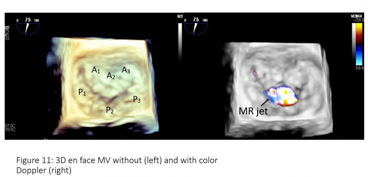
Figure 11: 3D enface mitral valve (left) and 3-D enface mitral valve with color Doppler flow mapping (right). Note: Mosaic color on the central of A2/P2 which is regurgitant jet location.
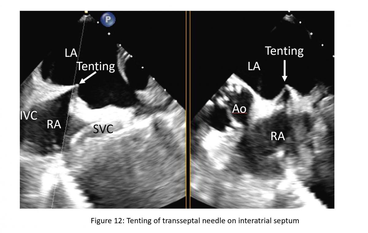
Figure 12: Xplane or biplane TEE view of bicaval and short-axis view of aortic valve for atrial puncture guidance. Tenting is hallmark of septal puncture need tip pressing on interatrial septum (IAS). LA: left atrium, RA: right atrium, SVC: superior vena cava, IVC: inferior vena cava.
The position of the BRK transseptal needle (St. Jude Medical, Inc, St Paul, Minnesota, USA) can be seen by a tent-like indentation of the interatrial septum (‘tenting’) (Figure 11) Thereby, the tip of the ‘tent’ points towards the left atrium. With a satisfactory posterior and superior location, the height above the valve is assessed in a four-chamber view (Figure 12).

Figure 13: 4-chamber TEE view from transeptal height (TS)
The site of optimal transseptal puncture is slightly different for PMR and FMR. In structural mitral leaflet disease (e. g. prolapse or flail), the puncture site needs to be 4–5 cm above the mitral annulus to guarantee enough space for adequate catheter and MitraClip maneuvering. In contrast, in cases of functional MR, the line of coaptation is usually below the plane of the mitral annulus due to extensive tethering. Therefore, the puncture site in these patients needs to be more inferior and closer to the annular plane (about 3.5-4.5 cm above the annular plane). Also, a different location of a lesion that cause MR may also require adjustment of septal puncture site (Figure 13).
Introduction of Steerable Guide Catheter (SGC) Into the Left Atrium
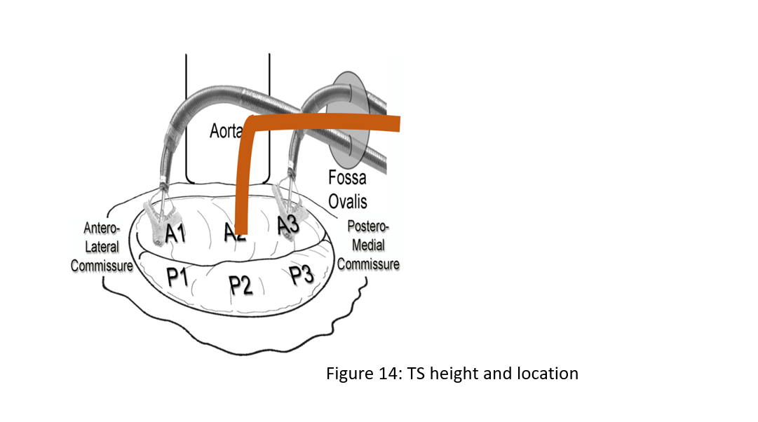
Figure 14: Transeptal height (TS) and location. Primary MR 4.0-5.0 cm, Functional MR with apical tethering of mitral valve leaflets 3.5-4.5 cm, Flail – higher, Lateral (A1/P1) – lower, Medial (A3/P3) – higher
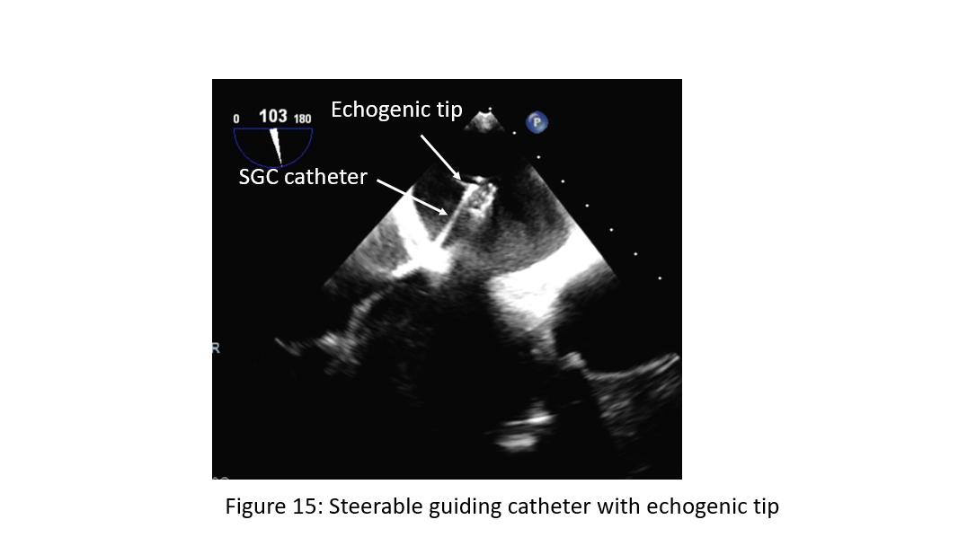
Figure 15: Steerable guiding catheter (SGC) with echogenic tip in left atrium.
The SGC with the dilator is gently advanced into the LA over a long stiff wire (placed in the left upper pulmonary vein) under fluoroscopic and TEE guidance. The dilator can be easily identified by a cone-shaped tip and a typical echogenic appearance of ridges on the catheter system with an echogenic spiral groove. A radiopaque echo bright double ring is characteristic of the tip of the steerable guide catheter (Figure 14). The advancement of the SGC should be carefully visualized under continuous 2D TEE (3D optional), and fluoroscopic monitoring to avoid injuries of the free left atrial wall. Often tenting occurring and resistance at the transition of the SGC/dilator is met. To avoid this, operators may consider change the dilator direction and if still unable to pass, consider pre-dilatation the septum with a 10 mm or 12 mm mustang balloon prior to introduction of SGC. Some operator will pre-dilate the septum up front as routine.
Once the SCG catheter sheath is safely placed approximately 2 cm in the left atrium, the extra stiff wire is retrieved first, followed by the dilator.
Advancement of the Clip Delivery System Into the Left Atrium
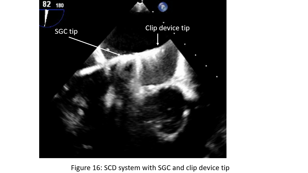
Figure 16: Steerable guide catheter (SGC) with introduction of clip device delivery system (CDS) with clip device tip towards left wall of the left atrium.
The CDS is advanced via the SGC under fluoroscopic guidance directed toward the left upper pulmonary vein. TEE is necessary to ensure that the tip of the steerable guide catheter remains across the interatrial septum and that the delivery system with the clip at the tip does not cause injury to the free left atrial wall or entering the left atrial appendage (Figure 15). As the CDS carefully exits the sheath it is required that the markers in the system straddle the sheath markers (Figure 16) before the clip can be moved toward the mitral valve. To position the CDS above the MV, a posterior torque of the SGC and simultaneous medial deflection of the CDS accompanied by retraction of the whole system are required. These steps are done under fluoroscopic guidance. After bypassing the pulmonary ridge and the floor of LAA, a gentle anterior rotation of the CDS accompanied with a simple lateral rotation brings the clip above the MV. The aim of this maneuver is to direct the clip in a horizontal direction as seen in the posteroanterior view fluoroscopically.
Location of Pathology and Positioning of the MitraClip
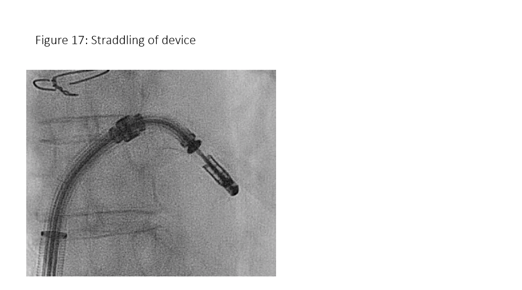
Figure 17: Mitral clip device straddled.
Medial-lateral clip adjustments and clip arm alignment are monitored in 3D enface view (Figure 17) upper left and lower left and right) and anterior-posterior adjustments in an orthogonal mid-esophageal biplane 2-chamber or commissure view and long-axis (LVOT) view (Figure 17). If the device is too far or close to the mitral valve, the device system would need to gain or reduced device height which can be manipulated by implanter to gain or shed height (Figure 3, I and J) accordingly. Similarly, if device is too medial or too lateral to the target lesion, implanter would need to adjust the device to the desire location and perpendicular (Figure 3 K) to the coaptation line at the lesion between anterior and posterior leaflet (Figure 3, C and D). To achieve good clip alignment, both arms of the opened clip can be visualized in full length in the long-axis view/LVOT view (Figure 17 right upper). The tip of the clip should be directed towards the largest proximal isovelocity surface area (PISA) or the location of mitral lesion. A single 3D enface view of mitral valve allows to determine if the clip is adequately positioned above the middle segments of the mitral valve and whether orientation is perpendicular to the line of mitral valve coaptation. Alignment of both arms perpendicular to mitral leaflet coaptation line is also checked with LVOT view with symmetrical and equal length of both arms. Location of the clip device is checked with commissural view for medial-lateral location and LVOT view for anteroposterior positioning.
Device Trajectory
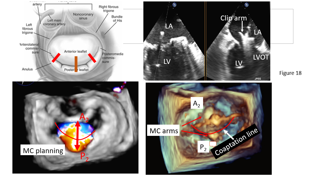
Figure 18: Clip arm orientation perpendicular to the coaptation line of each mitral leaflet component. Left upper: A schematic illustration of anterior and posterior leaflet coaptation line with assumed mitral clip perpendicular to A2/P2 coaptation in most common cases (solid line), in unusual case of mitral clip to A1/P2 or A3/P3 (dash line). Right upper: Biplane TEE commissure/LVOT view to demonstrate arm alignment perpendicular to mitral coaptation at A2/P2. Left lower: 3D en face mitral valve view with color Doppler. Note: central MR jet from A2/P2 coaptation. Lower right: enface mitral valve view showing mitral clip arm perpendicular to A2/P2 coaptation line.
The ideal trajectory should be parallel to the long axis of the heart and perpendicular to the mitral valve opening. If necessary, the trajectory can be modified by orienting the SGC in anterior or posterior position and by adjusting the medial knob of the CDS in medial or lateral position or pulling back or advancing the entire device system (Figure 3 H). The trajectory is checked on orthogonal two plane view of 2D TEE (X-plane view); the intercommissural view, and the left ventricular outflow tract (LVOT) view (Figure 18), obtained on top of the clip. 3D TEE can be helpful if 2D TEE is uncertain.
In the routine practice, it is recommended to pass the opened clip into the left ventricle (6). In our experience, passing the mitral valve with an opened clip will require reassessment of the orientation of the clip again as the clip may rotate during translation from the left atrium to the left ventricle prolonging the procedure (7). Some operators prefer to advance the clip closed at the site of the regurgitant jet under the mitral leaflets in the LVOT view under breath holding. A correct orientation of the MitraClip, with perpendicular alignment to the line of coaptation, verifying that both mitral leaflets are freely moving above the clip arms, is crucial for a successful grasp of the mitral valve leaflets. 3D enface mitral valve view with reduced gain setting to eliminate mitral valve echo and to visualize clip arm in the LV under mitral leaflet will be used to confirm the orientation of the arm if there is suspicion of arm misalignment.
Movement in the LV Should be Limited to Avoid Choral Entrapment
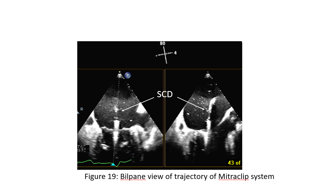
Figure 19: Bilpane view of trajectory of Mitraclip system. Note: clip device delivery catheter is perpendicular to mitral annulus plane in a biplane TEE view of commissure and LVOT.
Relatively chord free zone is at the center of A2 and P2 coaptation zone. There is a more complexed chordal apparatus away from the center. The more away from the center of A2/P2 the more complicated chords (primary, secondary, tertiary) (Figure 19). Thus, the clip device should be positioned at the center of the chordal free zone if there is A2/P2 central lesion. Chordal entrapment can occur with the clip arm off center of A2/P2 in the vicinity of chordal complex zone of P1/A1, P3/A3. In this case, implanter should
- Invert the clip and retract into the left atrium
- Raise and/or lower the grippers
- Undo all maneuvers that led to the entrapment
- Attempt to advance into the ventricle
- Place on the chordal apparatus
- Convert to surgical procedure if appropriate grasping leaflet is not possible.
Grasping of the Leaflets, Assessment of the Result, and Clip Release

Figure 20: Mitral leaflet and chordal complex. Note: relatively chordal free zone at the center of A2/P2 and complex chordal system (primary, secondary and tertiary chords) progressively towards commissural sides. AML: anterior mitral leaflet, PML: posterior mitral leaflet, LAA: left atrial appendage, A1A2A3 of anterior mitral segment from lateral to medial, similarly, P1-P3 of mitral leaflet from lateral to medial.
Once the MitraClip is in a satisfactory position, gently and slowly pulling back toward mitral annulus under TEE monitoring. grasping of the leaflets as they are falling into and captured in between the clip arms by lowering the gripper which is monitored using a 2DTEE LVOT view (Figure 20). It is recommended to do this with the help of a short breath-hold, controlled by the accompanying anesthesiologist. After capturing both leaflets with both arm of the device, grasping of the leaflets accomplished by lowering the gripper and partially closing the clip to secure leaflet insertion. During clip alignment with 3D enface view of mitral valve perpendicular to the coaptation line of anterior and posterior leaflet where the regurgitant lesion is located, it is vital to find the corresponding view in 2D-TEE, where both arms of the clip are visible above the mitral valve during arm alignment and below the mitral valve after entering the LV. By doing this we define the correct angle in 2D-TEE in which we have to gasp the anterior and posterior leaflet in the area where the PISA and vena contracta is largest. Combination of 3D and 2D TEE views are the best and most simple way to ensure safe clipping with proper perpendicular alignment to the line of coaptation in the regurgitant area without significant risk of valve distortion and significant stenosis.
Multiple planes are useful for assessment of proper leaflet insertion into the MitraClip. The insertion of the posterior leaflet is commonly best seen in the LVOT view, and the insertion of the anterior leaflet in the LVOT and the four-chamber view. The intercommissural view can add information such as entrapped chordae tendineae and lateral-medial location of the clip. After grasping of the leaflets, leaflet capture is evaluated by lowering the gripper and partially closing the clip to secure leaflet insertion (Figure 20). Formation of the double- barrelled orifice is confirmed with an enface view to make sure that each orifice is approximately the similar size (can be different size depending on MR jet location) and both posterior and anterior leaflet are adequately grasped with adequate tissue bridging. Stability of clip position without excessive motion and adequate length of tissues grasp are assessed by multiple views of 2D TEE and 3-D TEE enface view of mitral valve from both atrial and ventricular sides.
Assessment
| Result |
|
| Grasp |
|
| Questions |
|
Before and after the implantation of each clip, it is necessary to evaluate the grade of residual regurgitation and stenosis of the mitral valve with mean gradient < 6 mm Hg, and in addition, the morphological results and grade of residual MR after clip placement [6]. Effort should be made to reduced MR to less than moderate or 2+.
Residual MR can be easily graded by color Doppler, but it can be challenging at times. It has to be taken into consideration that the area of color jets is larger with multiple jets, which commonly occurs after a MitraClip is implanted (due to the addition of multiple jet areas), than if there is a single jet [8]. This may potentially lead to overestimating residual MR in patients with multiple jets. Vena contracta of MR jet or origin of MR jet width immediately adjacent to atrial side of mitral valve maybe used to assess severity of residual MR. Similarly, PISA can also be used. 3D enfance mitral valve with color Doppler flow may be helpful for assessing vena contracta and 3D PISA. Pulmonary venous flow pattern which reflects change in left atrial pressure or V-wave of left atrial pressure can be used to assess change of hemodynamic effect of residual MR. It is common that significant reduction of MR leads to recovery of systolic pulmonary venous flow from reversal or blunting or even normalize pulmonary venous flow pattern. Significant reduction of MR often leads to increase or new appearance of “smoke” in the left atrium or appendage. Measurement of the pressure curves in the left atrium to measure the height of the V-wave before the procedure and compare it with the pressure curves after implantation of the MitraClip can also be helpful if there is a catheter in the LA. However, additional catheter in the LA often adds to procedural time and cost. On the other hand, angiographic MR grading may be inaccurate if the catheter is entrapped in the chordae tendineae, if insufficient contrast is used to pacify the left ventricle and left atrium, or in the presence of arrhythmias [9].
Tips and Pitfalls
Implantation of additional MitraClips is not uncommon during mitral clip procedure, accounting about 30-50% in most published data. It may be fewer with newer clip of XTR. However, effort should be made to an optimal correction of MR if possible, with an optimal MitraClip placement to maximize the benefits of the procedure and minimalize the risk of adverse outcomes and undesirable increase in mitral valve gradient. Residual MR of moderate or more after MitraClip is associated with higher mortality than that for patients without significant residual MR [10].
If there is a significant residual MR without significant gradient across mitral valve (mean gradient < 5 mmHg), a second clip is usually considered if anatomically feasible. The orientation of the second clip is mostly done predominantly fluoroscopically with use of 3D TEE (Figure) for arm orientation before going into LV and should be aligned as parallel as and as closer as possible to the first clip both watched by fluoroscopy and TEE. During advancement of the MitraClip from the left atrium into the left ventricle under breath-holding, the clip should be closed to avoid any interference or entanglement with the chordae tendineae then re-opened in the left ventricle. Folding of leaflet tissue between two MitraClips should be avoided as this may cause uncorrectable residual MR [6].
Conclusion
The MitraClip procedure is rapidly evolving as an important option among the current therapies for MR. The safety profile of this device appears to be good and data from heart team in experienced center have shown that reduction of the severity of MR is achievable in most if not all patients with low in-hospital complications and significant clinical improvement. Patient selection, accurate assessment of severity of MR by echocardiogram or cardiac MRI if uncertainty with echo, and thorough pre-operative planning with detailed morphological assessment by TTE and TEE, in some instance, cardiac CT are prerequisite for successful mitraclip implantation. TEE plays the major role in guidance of the procedure and assessment of residual MR and optimal clip placement
Future New Imaging Technology with Fusion Imaging
Multimodality imaging (i.e., side-by-side registration of data rendered by more than 1 noninvasive imaging modality, such as echocardiography, advanced computed tomographic technologies, angiography, and cardiac magnetic resonance) may increase diagnostic accuracy by combining anatomic, morphological, and functional information. Thus, some of the limitations of stand-alone imaging modalities can be overcome. As pre-procedural assessment, procedural guidance, and post-procedural evaluation of mitral interventions currently rely heavily on echocardiography, the real-time fusion of echocardiography and fluoroscopy is of particular importance. Technology that automatically recognizes and tracks the position and shape of the transesophageal probe in the fluoroscopic image form the basis of this technology. Whenever fluoroscopy is used, fusion imaging can identify the position of the probe by tracking the shape and the direction of the probe within the fluoroscopic image, thus enabling a relatively accurate overlay of different imaging modalities such as 2D and 3D TEE, color Doppler, and partial thickness upon the fluoroscopic image. Fusion may improve the safety of the transseptal puncture and other procedural steps during percutaneous MV repair using the MitraClip. New technologies that synchronize echocardiographic and fluoroscopic imaging could potentially simplify and optimize procedural guidance, improve the degree of MR reduction, and enhance safety as well as shorten the duration of both fluoroscopy and the procedure.
References
- Senni M, Adamo M, Metra M, Alfieri O, Vahanian A. Treatment of functional mitral regurgitation in chronic heart failure: can we get a 'proof of concept' from the MITRA-FR and COAPT trials? Eur J Heart Fail. 2019 Jul;21(7):852-861.
- Arnold SV, Chinnakondepalli KM, Spertus JA, Magnuson EA, Baron SJ, Kar S, et al. Health status after transcatheter mitral-valve repair in heart failure and secondary mitral regurgitation: COAPT trial. J Am Coll Cardiol. 2019 May 7;73(17):2123-2132.
- Stone GW, Lindenfeld J, Abraham WT, Kar S, Lim DS, Mishell JM, et al. Transcatheter mitral-valve repair in patients with heart failure. N Engl J Med. 2018 Dec 13;379(24):2307-2318.
- Feldman T, Foster E, Glower DD, Kar S, Rinaldi MJ, Fail PS, et al. Percutaneous repair or surgery for mitral regurgitation. N Engl J Med. 2011 Apr 14;364(15):1395-1406.
- Biner S, Perk G, Kar S, Rafique AM, Slater J, Shiota T, et al. Utility of combined two-dimensional and three-dimensional transesophageal imaging for catheter-based mitral valve clip repair of mitral regurgitation. J Am Soc Echocardiogr. 2011;24:611–617.
- Wunderlich NC, Siegel RJ. Peri-interventional echo assessment for the MitraClip procedure. Eur Heart J Cardiovasc Imaging. 2013;14:935–949.
- Bhattacharya S, He Z. Mechanics of mitral valve edge-to-edge- repair and MitraClip procedure. J Long Term Eff Med Implants. 2015;25:135–145.
- Quaife RA, Salcedo EE, Carroll JD. Procedural guidance using advance imaging techniques for percutaneous edge-to-edge mitral valve repair. Curr Cardiol Rep. 2014;16:452.
- Grayburn PA, Weissman NJ, Zamorano JL. Quantitation of mitral regurgitation. Circulation. 2012; 126:2005–2017.
- Paranskaya L, D’Ancona G, Bozdag-Turan I, Akin I, Kische S, Turan GR, et al. Residual mitral valve regurgitation after percutaneous mitral valve repair with the MitraClip(R) system is a risk factor for adverse one-year outcome. Catheter Cardiovasc Interv. 2013 Mar;81(4):609-617.
Disclosure
Mark Russo: Speaker Bureau: Edwards Life Sciences
Disclaimer
The information and views presented on CTSNet.org represent the views of the authors and contributors of the material and not of CTSNet. Please review our full disclaimer page here.


